
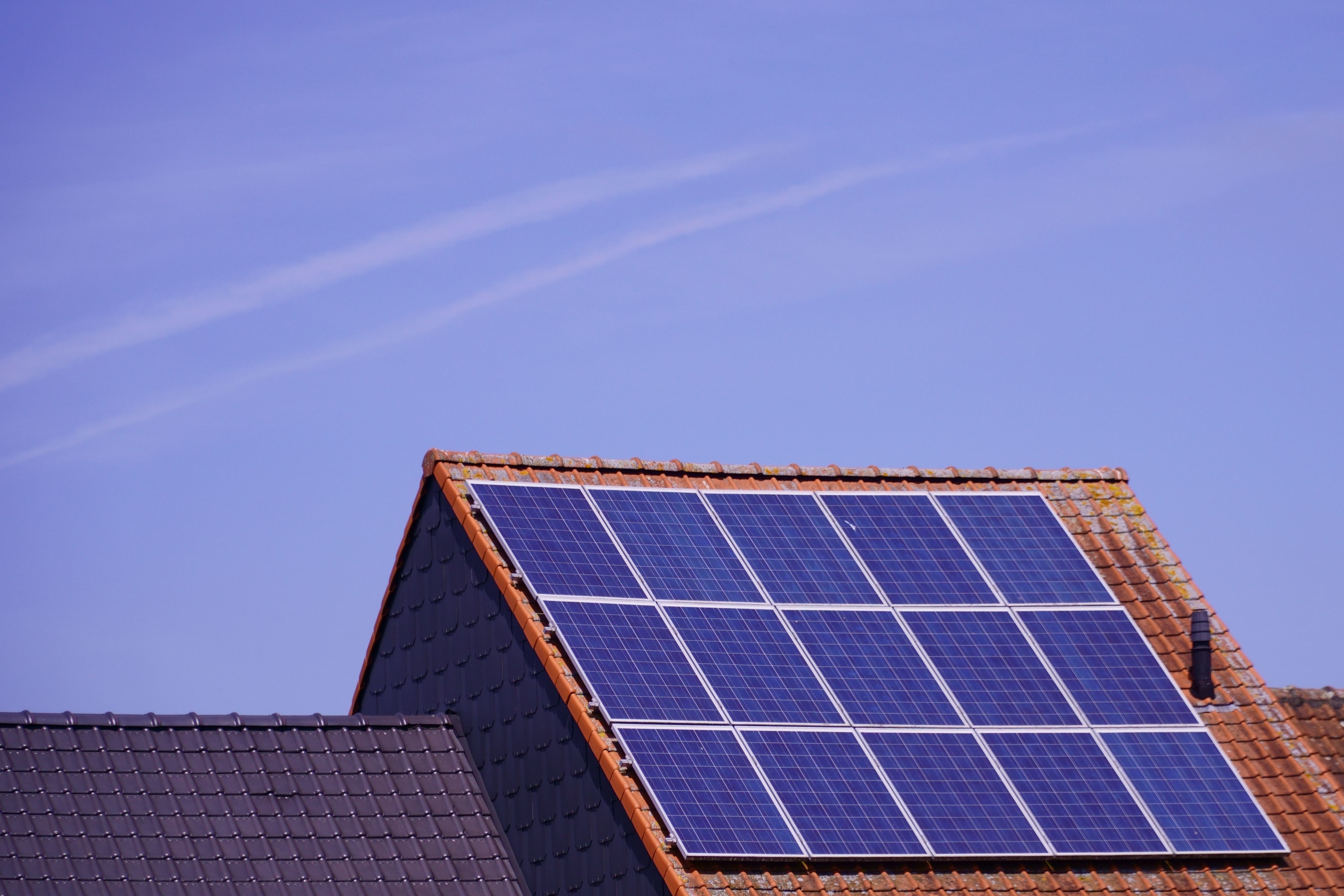
When planning a solar installation, the first decision is choosing where to mount the panels. While rooftop arrays represent the vast majority of residential installations due to convenience, properties with large yards or complex roofs often benefit from ground-mount solar arrays.
However, from a structural and electrical engineering perspective, these two system types are completely different. Ground-mount projects face more stringent zoning rules, trenching requirements, and soil-specific calculations that require licensed engineering support.
1. The Structural Split: Roof vs. Ground
Rooftop systems rely on an existing building structure. The engineer's primary job is verifying that the pre-built rafters can support the additional weight (dead load) and uplift forces. Ground-mount arrays, on the other hand, are freestanding structural buildings. They require custom steel or aluminum racking frames anchored directly into the earth, which triggers full foundation design requirements.
2. Ground Mount Foundations & Soil Classifications
Ground-mount arrays must resist wind uplift trying to pull the structure out of the ground, and gravity loads pushing it down. The foundation design is governed by the property's soil class:
| Foundation Option | Design Details | Soil Condition Compatibility |
|---|---|---|
| Concrete Piers (Post-in-Concrete) | Steel posts cast inside deep, vertical drilled shafts (typically 5 to 10 feet deep). | Most common; ideal for clay, silt, and cohesive soils. |
| Helical Screws (Ground Screws) | Threaded metal posts screwed directly into the ground using heavy machinery. | Ideal for rocky soils where drilling deep piers is difficult. |
| Ballasted Trays | Heavy concrete blocks sitting in trays on the surface of the ground. | Used on landfills or brownfields where breaking ground is prohibited. |
To secure a ground-mount permit, your plan set must include structural calculation sheets specifying concrete volume, rebar sizing, and steel post thickness stamped by a registered structural P.E.
3. Long Trench Runs & DC Voltage Drop Sizing
Because ground-mount systems are located further from the main utility service meter than rooftop systems, they require long underground trench runs. This introduces two critical engineering considerations:
- NEC 300.5 Burial Depth: Circuits must run through underground conduits. Conduits under lawns must maintain a burial depth of at least 18 inches for PVC or 24 inches for direct-buried conductors.
- Voltage Drop Calculations: Direct current (DC) running long distances suffers voltage drop, which reduces energy production. Engineers must upsize the copper or aluminum conductors to keep total voltage drop under 2-3%.
4. Zoning Setbacks & Property Boundary Clearances
Municipal zoning codes regulate ground-mount installations much more strictly than roof mounts. Local AHJ zoning codes define:
- Property Line Setbacks: Canopies must remain a specified distance (typically 5 to 15 feet) from side and rear property lines.
- Height Limitations: Most residential zoning boards limit ground array heights to 10–15 feet above grade to avoid blocking neighbor views.
- Lot Coverage Limits: The surface area of the ground-mount canopy is factored into the property's maximum allowable accessory building coverage ratio.
5. Picking the Right System Design
At Daniel Solar Engineering and Design, we handle the complete engineering lifecycle for both ground-mount and rooftop solar arrays. We prepare complete structural foundation diagrams, calculate DC/AC voltage drop wire parameters, and design code-compliant single-line layouts stamped by licensed civil and electrical P.E.s across all 50 U.S. states.
PLANNING A GROUND-MOUNT SOLAR INSTALLATION?
Contact Daniel Solar Engineering and Design today. Our engineering team prepares stamped structural foundation plan sets and trenching layout calculations for residential and commercial ground arrays.